Traditional shortwave receivers use variable capacitor tuned LC circuits in preselector or RF amplifier stages as well as the local oscillator. The value of minimum and maximum capacitance of a variable capacitor is predermined, as well as the ratio between them, so it is cosidered as initial condition of the design proces. The capacitance ratio in conjunction with other factors, like oscillation conditions of a given local oscillator construction, reduces the achiebable tuning ratio with a given inductance value – typically somewhere around a 1:2.5 … 1:3.5 range. Because of this, the 0.5…30 MHz tuning range of a MW/SW receiver is broken down into several tuning bands. The number of bands is a compromise between build cost, easy tuning and frequency stability.
To match exactly the the frequency ranges of RF and LO stages, L and C values are built trimmable. The inductance has an adjustable coil, and additional fixed and trimmer capacitors are used in parallel to the main variable capacitor.
Objectives
With this little experiment, my goal was are to find decent band breakdown, and to calculate ideal L and C values for each band.
Determining L and C Values for a Given Band
Let the minimum and maximum capacitance of the variable capacitor (same for all bands), and the angular frequencies for the band.
We are looking for the inductance value and parallel (fixed + trimmer) capacitor value of each LC circuit for each band.
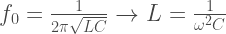
From the Thomson-formula, we can express L, the inductance for our LC circuit:
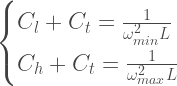
For a given band, when we tune to the bottom of the band, the following should hold:
Similarly, tuning to the top of the band, the following should also hold:
From this, we can deduct :
.
Just like that, we can also deduct L by expressing C for both ends of the band:
Deducing L:
Example
Let’s say our variable capacitor has and .
The MW band has kHz, and MHz. For the RF amplifier, we will get . The tuning ratio will be 2.96. can be constructed using a 22pF fixed capacitor and a trimmer capacitor with around 22pF maximal value. L and C for the local oscillator can be calculated by shifting the frequency range by the desired intermediate fequency.
I have bought this thing a couple years ago at a hamfest for a few pounds. I wanted something on my desk that I can use for my vacuum tube experiments. It fits the bill, it tolerates high voltages well, and has high enough input resistance, so I took it home.
At hamfests, if you ask the seller if the equipment you laid your eyes on is working, they will always say yes, if any light comes on in the front panel when it is powered up. I bought a few old piece of gear for cheap, and every time I asked I had the same answer. How they actually worked in reality, was another story.
This one was in a fairly good shape, it actually powered up, all the tubes were lit inside, and it showed signs of life in all possible ranges. It was not accurate nor stable of course, but I did not expect that from a gear more than 60 years old. So I thought I will give it new caps and see how it goes.
First, I did some research to find the correct documentation. I have found a schematic for the variant B, which is apparently very similar, the only significant difference is that it lacks of a regulated power supply, and probably because of that, the internal voltages are slightly different.
The Old Caps Must Go
The disassembly was fairly simple, after removing the right screws, it has fallen apart to three large pieces, and all the internals became accessible. I quickly made a list of the caps inside, and put my order online. So I thought. Usually, caps for the same spec manufactured these days are significantly smaller in size than the ones you can find in old equipment like this. Not my package which apparently had one cap inside with the size of a practicing hand grenade, making the whole parcel too big to fit through my mail slot. It seems that what supposed to be a 3000 μF/25V was actually a 3000μF/400V cap. I checked my order, and yes, it was my mistake. I thought that was for HV, but no, it is in the low voltage section. So now, I have a spare steam roller if I or anybody else ever need that capacity, for like a railgun or something. Just because I do not have enough unnecessary crap lying around already. 😀
The New Ones Installed on Tag Strips
Whatever, I replaced the caps and turned the thing on. In the meantime, I have managed to find the correct service manual online so I could check the power supply voltages. In this thing even the heating voltage is regulated! That part was actually fine, but the HV regulator was off and I could not set the right voltage. It is quite a textbook regulator with a cold cathode tube as a voltage reference. So I checked the voltages at the important places. Apparently, the regulator could not reach its working point, and the reason for that was the voltage coming from the rectifier was not high enough.
Those brown cubes are the selenium rectifiers. They smell….
As it seems, they used old-fashioned selenium rectifiers in the power supply and they deteriorated. The dead giveaway is the smell they produce (which is actually the smell of toxic fumes so do not inhale it if you bump into something like those). So I replaced them with a pair of HV silicon diodes, but this time it produced too high voltages for the regulator.
In contrast to silicon diodes, which have approximately 0.6…0.7V voltage drop across their terminals when they are conducting, selenium rectifiers has a several tens of voltage drop, and I had to simulate this somehow, so I added a few hundred ohms of resistors in series to the diodes to reach the same. It has the additional advantage to protect the diodes from the inrush current when the buffer caps are charged the first time when the unit is powered up.
Silicon diode + resistor combo as a selenium rectifier replacement
It worked out nicely, but I still could not set the regulated voltage. So I have checked all the tubes, and the resistors, and I found that one of the resistors were way out of tolerance. After I replaced it, the power supply suddenly started working as expected. Yay!
After setting the correct supply voltage, everything seemed ready to start re-calibrating the instrument. I mean…., set it as accurate as I could, lacking a proper, calibrated voltage source or voltage meter. Having only a crappy old DMM and a cheap Chinese panel meter built in to my HV power supply, I did not have many options. Actually these two agree on voltages pretty closely, so “statistically” they are accurate enough, I guess….
So I started to go through the calibration process detailed in the manual. At Marconi, they used these awful slider trimmer pots in this instrument, and all of them were glued down with some substance. I had to remove that, and I think I made a mistake when I did not wait long enough for the alcohol to dissolve the glue. Apparently, the carbon stripe cracked somewhere in the middle in one of those pots. I only realised it after I finished with the first half (DC) part of the process. I managed to find a replacement, and started the entire process again. And again, and twice more, because these things are touchy and I accidentally moved the ones I previously adjusted.
The bad resistor was the 200K one. The end cap fell off when I removed it.
During the process, I discovered that the whole instrument was still unstable. Even after I set zero several times, the needle started wandering around a few marks. Something was crumbling in there, but what? To find out, I took my hot air gun, and started to blow narrow stream of hot air into different parts of the instrument. After a few trials, it turned out, that a resistor in the differential DC amplifier caused the problem. It pushed the amplifier out of balance every time the temperature changed. It was in so bad shape, it fell apart as I unsoldered it. I put in a new one, and for the sake of symmetry, I replaced the counterpart of it at the other tube. Now the instrument was much more stable.
As I went through all the calibration once again, and checked the different ranges, a couple things became apparent. First, probably some of the fixed high-precision resistors are out of their tolerance, but my DMM is incapable of measuring accurately enough to judge, or even measure it at all in that range, so I have to wait until I get a better multimeter. Second, some of the potentiometers setting the zero levels are scratchy, even after some nice bath of DeOxit, so they have to go as well. But I think I will wait until I have enough issues with this VM to sit down and take it apart again.
Despite all of that, the instrument became stable and accurate already enough to be useful and measure some basic things I wanted.
So here it is, with its current state, with all the bad components I replaced.
I hope you enjoyed this little adventure with me and hopefully I could provide you some useful information about this instrument or about the process.
Since SWL is in one of my main interests, but I never had enough space to build a full-sized receiving antenna system, it seemed like a good idea to build something which takes up significantly less space. One option was a magnetic loop, but it still needs some space, and some extra equipment to build it (soldering copper pipes together with a blow torch is not entirely compatible with my current accommodation). Not to mention that a magloop needs constant adjustment in orientation and also tuning. When I saw that the most popular SW SDR receiver stations on websrd.org uses mini-whip active antenna, I decided to give it a try.
I rebuilt PA0RDT’s active antenna [1], improved by PA3FWM [2], but i did not bother to make a properly etched PCB, I just used a breadboard. The receiving surface is a piece of sheet aluminium, 0.5 mm thick, held by two screws at the edge of the board. The build was quite straightforward. The connector is a 50 ohm BNC, which carries the signal towards the receiver, and also the power to the antenna unit.
The finished antenna. I did not give it a proper housing since I intend to use it indoors only. Maybe later I will build it into a PVC pipe or something like that. The zip tie on the end is for mounting.
The circuit worked nicely, but achieving good reception needed some extra effort and tweaking in the power supply box, and some trial and error to find the right location to the antenna.
As the original article states it, finding proper grounding is vital for good reception. I do not have an opportunity to put the antenna outside the house, so local QRM is quite a concern.
One of the most important thing was to find the right location for the antenna. Interestingly, it is not as intuitive as it seems. To put it as high as possible is a good rule of thumb, but there might be also some hot spots within a room at locations near well grounded objects, like radiators, metal structural elements, etc., so it is always a good idea to try all the available locations thoroughly.
An important thing to consider is that you have to look for S/N ratio instead of absolute signal strength, especially if it installed indoors. The active antenna has a well enough gain to easily overdrive a receiver if the probe surface is large. I have an FRG-7, which is not so great in terms of large signal handling. It is easy to find a spot where the S-level is high, but it is much harder to find one when you can actually hear weak stations.
Another issue for me was feeding the unit. The mini-whip is quite susceptible to pick up local noise coming through the feed line from the receiver end. In order to reduce this, I have done a few countermeasures. The first and most important thing was to connect the outer shield of the coax to a good grounding point close to the mini-whip. The best grounding point I could find was the valve of the radiator under the window of my room. I also added those noise suppressor clip-on cores to the coax, after the grounding point. I made a few turn coil from the coax as well, to further increase the the choke effect.
I also modified the original feeding unit by separating the antenna ground from the receiver ground by installing a wideband RF transformer to the receiver side, and connect the receiver cable via an ground isolated BNC connector [3]. It reduces the noise coming from the direction of the receiver and also breaking the ground loop. I also added two chokes to the connection towards to the +12V power, to both the positive and negative wire, so the shield of the power unit is not grounded through the +12V PSU any more. I connected the shielding of the power unit directly to the ground.
Not a winner in a beauty contest, but works well. The two green chokes are nicely visible towards to the PSU plug. I left out the resettable fuse. Maybe I will add it later.
After all these modifications, the overall noise is much lower than before, though there is still some 50Hz modulated noise on some frequencies, and I could not find the source of it yet, even if I turned off all the possible noise sources nearby, one by one.
In general, the antenna gives quite good reception, despite of it is located inside my room. I found a final place for it where it (usually) does not overdrive my receiver, and the noise level is reasonably low.
SWLing with the new antenna. It works pretty good. 🙂
Impedance matching between a transmitter and an antenna is essential. You can even kill your PA if the reflection is too high and much of the energy is reflected back. But it can be important to match your antenna with your receiver, too, in order to reach the best possible reception.
So I decided to build my own tuner (instead of buying one) for my receiver experiments. My choice was the ubiquitous T-match, because it can match wide range of antenna impedance, and it is simple to build.
Since there are no significant power requirements against the tuner, I could use variable capacitors with any voltage rating. So I bough two of those they use in pocket radios. The exact value does not matter too much until it is in the 400-600 pF range somewhere.
I built the coil using a big yellow Amidon core I bought a long time ago. The winding can be calculated using toroids.info. In my design I made a tap after each 6th turns, there are 11 terminals in total. The resulting inductance range is adequate for my purposes.
One of the benefits of this construction that the terminals can be soldered directly to the switch, no extra mounting or wiring necessary. It greatly simplifies the overall construction and needs no extra mounting and wiring.
The usual blissful mess…. 🙂
I built the whole thing into those die-cast alloy cases. It is a great EMI shield, does not allow dust to get in, and very sturdy, so the whole unit can be used even outdoors on a field day or a hiking. It is not waterproof, of course, but it was not the goal anyway.
I went for 50 ohm BNC connectors, because most of my cables and receivers use that.
The components are a tight fit, so I had to be careful to put the holes exactly to the right place, which was not always easy. There was no room for much play. There were only millimetres between the components and the box. Also, the axles of the switch and the capacitors made it nontrivial to mark the precise location of the mounting holes.
It cannot be seen, but it stands on those self-adhesive rubber feet. It is a really nice addition, it greatly hepls to keep the unit in place when a bit heavier cables are attached. It also protects the paint on your receiver if you put the ATU on the top of it.
This little gadget works pretty well. I tested it using a random long wire and a RTL SDR receiver. Seeing a wide spectrum is very useful, you can see how the noise floor changes as the resonance sweeps through as you adjust the tuning. The tuner adds quite good signal boost in most cases. It also helps reducing receiver overload, since it acts like a (not too sharp) preselector, suppressing strong signals out of the band.